All About Electrical Wiring Types, Sizes & Installation
Understanding the basics of electrical wiring is crucial for anyone planning electrical projects. Knowledge of wiring materials, installation techniques, and terminology is essential for safe and successful projects. Identify and select appropriate wires, cables, and connections to troubleshoot and install electrical systems effectively. Whether tackling repairs or embarking on new projects, a solid grasp of wiring fundamentals ensures efficient and safe electrical work.
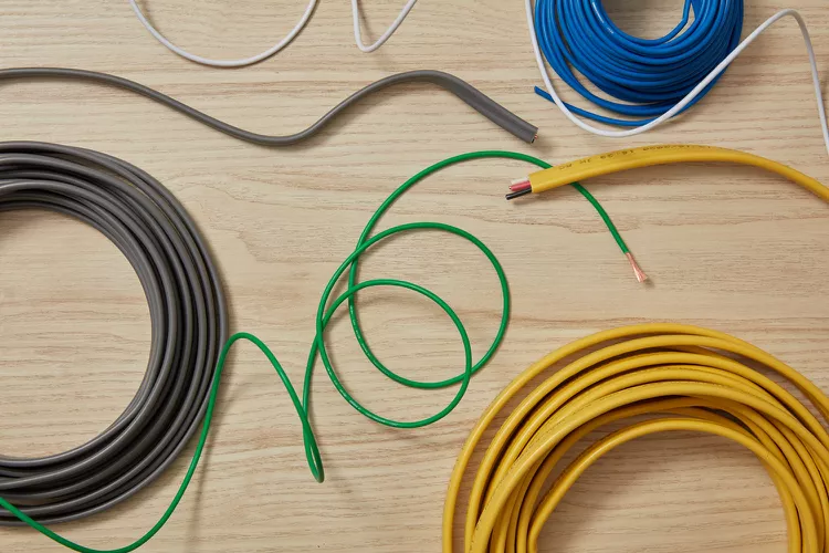
Here are all the basic elements you need to understand about electrical wiring.
Wire Sizing
Absolutely, choosing the correct wire size is crucial to ensure the safety and efficiency of electrical installations. Here are some key points about wire sizing:
- American Wire Gauge (AWG): The AWG system is the standard for wire sizing in the United States. Smaller gauge numbers indicate larger wire diameters and higher ampacity.
- Current-Carrying Capacity: The ampacity of a wire refers to the maximum current it can safely carry without overheating. This is determined by factors such as wire size, insulation type, and ambient temperature.
- Matching Wire to Amperage: Wires should be selected based on the anticipated current load of the circuit they serve. Using a wire with insufficient ampacity can lead to overheating and potentially cause a fire hazard.
- Circuit Protection: Fuses or circuit breakers are used to protect electrical circuits. The rating of the protection device should match or be lower than the ampacity of the wire it is protecting.
- Consider the Application: Different applications may require different wire sizes. For example, household lighting circuits typically use smaller gauge wires than those used for major appliances.
- Voltage Drop: In long wire runs, voltage drop becomes a consideration. Larger wire sizes may be required to minimize voltage drop and ensure proper performance of electrical devices.
- Wire Insulation: The insulation type is also important, as it affects the wire’s ability to handle specific environments and conditions.
Always consult local electrical codes and regulations, and when in doubt, seek the guidance of a qualified electrician for proper wire selection and installation.
Non-Metallic (NM) Sheathed Cable
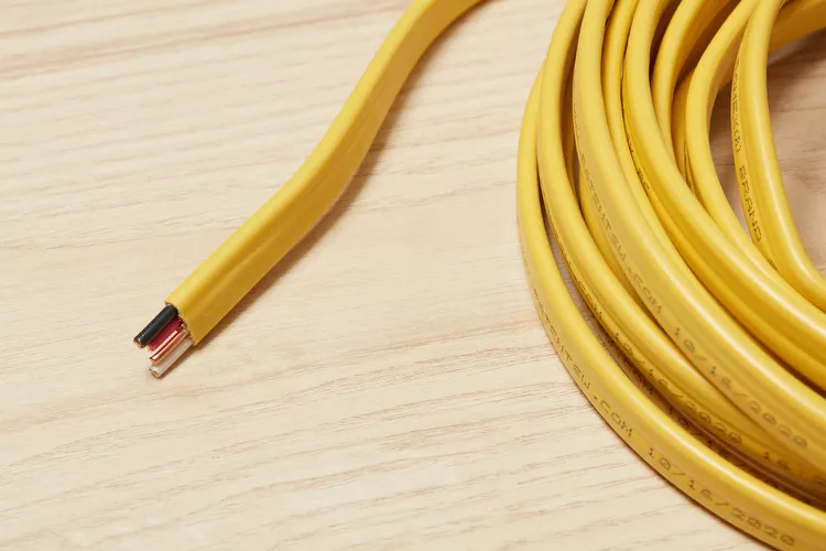
Understanding the basics of NM cable (Non-Metallic cable) is essential for electrical projects. Here are key points about NM cable:
- Composition: NM cable consists of multiple wires enclosed within a flexible plastic sheathing. The most common types include two or three insulated wires and a bare ground wire.
- Popular Brand Name: Romex is a widely recognized brand name for NM cable. It is often used interchangeably with the term NM cable.
- Interior Wiring: NM cable is primarily used for interior electrical wiring. It is suitable for various applications within a building, including outlets, switches, light fixtures, and appliances.
- Insulated Wires: The insulated wires within the cable can be color-coded for identification. Common colors include black (hot), white (neutral), and bare or green (ground).
- Sizes and Configurations: NM cable comes in different sizes and configurations, with the number of wires and their gauge determining the cable’s capacity to carry electrical current.
- Protective Sheathing: The plastic sheathing provides protection to the enclosed wires, preventing damage and ensuring safety. It also simplifies the installation process.
- Installation Guidelines: Proper installation is crucial for safety. NM cable should be secured and supported, follow the correct bending radius, and avoid exposure to potential hazards.
- Code Compliance: Adherence to local electrical codes and regulations is essential when using NM cable. Codes may dictate the type of NM cable suitable for specific applications and locations.
Before undertaking any electrical project, it is advisable to consult local electrical codes, follow safety guidelines, and seek professional advice if needed.
Electrical Wire Color Coding
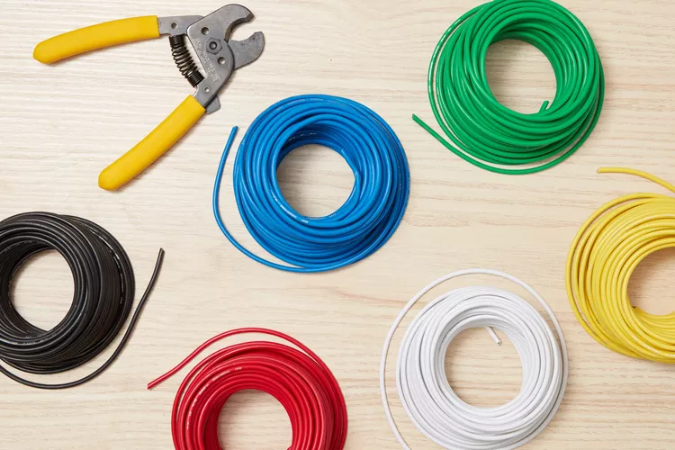
Understanding the color coding of electrical cables is crucial for identifying their purpose and maintaining consistency in electrical systems. Here are key points about color coding:
- Outer Sheathing Color Coding: The color of the outer sheathing of bundled electrical cables often indicates the cable’s size and amperage rating. For example:
- White-sheathed NM cable is typically used for 15-amp circuits.
- Yellow NM cable is commonly rated for 20-amp circuits.
- Individual Conductor Color Coding: The color of individual conducting wires within a cable or conduit serves specific purposes:
- Black and Red Wires: These colors are typically used for current-carrying or “hot” connections.
- White Wires: White wires are usually designated for grounded “neutral” conductors.
- Green-Insulated and Bare Copper Wires: These wires are specifically used for grounding.
- Amperage Rating Consideration: The color coding on outer sheathing aligns with the amperage rating of the cable. It helps users easily identify the capacity of the electrical circuit.
- Consistency and Standardization: Following color coding standards ensures consistency in electrical systems, making it easier for electricians and homeowners to understand and work with the wiring.
- Safety and Identification: Proper color coding contributes to safety by clearly indicating the function of each wire. It aids in troubleshooting, maintenance, and repair processes.
- National Electrical Code (NEC): The color coding standards are often outlined in the National Electrical Code (NEC) or other local electrical codes. Adherence to these codes is essential for compliance and safety.
- Grounding Wires: Green-insulated wires and bare copper wires are specifically designated for grounding purposes, contributing to the safety of the electrical system.
Understanding and following color coding standards is fundamental to safe and effective electrical work. Users should consult relevant electrical codes and guidelines to ensure compliance and best practices in wiring installations.
Electrical Wiring Labeling
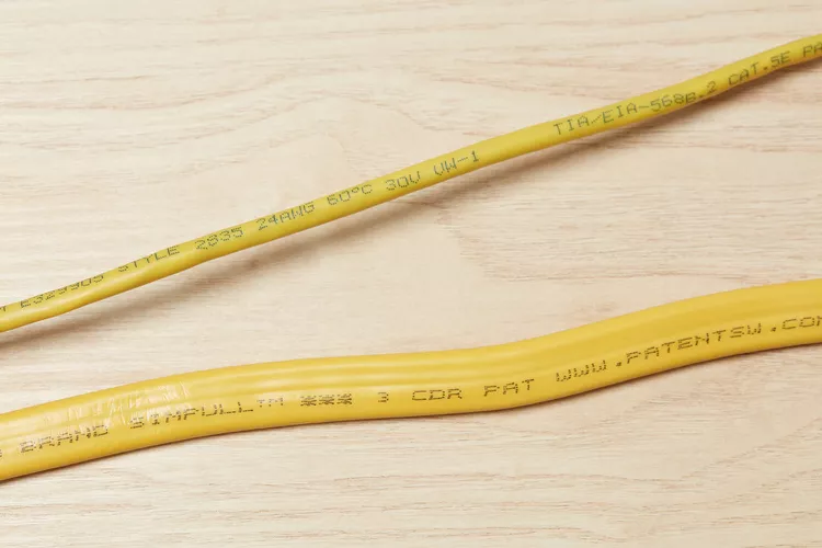
Deciphering the markings on electrical wires and cables is crucial for understanding their specifications and ensuring their appropriate use. Here are key insights into interpreting these markings:
- Wire Size and Material: Markings often indicate the wire size (gauge) and the material used. For example, “12 AWG CU” signifies a copper wire with a 12-gauge size.
- Insulation Type: Information about the type of insulation is provided through markings. For instance, “THHN” stands for Thermoplastic High Heat-resistant Nylon-coated wire.
- Number of Wires: In the case of cables containing multiple wires, markings reveal the count and arrangement. A marking like “2C” denotes a two-conductor cable.
- Special Ratings: Special characteristics or ratings, such as temperature resistance, moisture resistance, or flame-retardant properties, are often specified in markings. “XHHW-2” indicates a cross-linked polyethylene high-heat-resistant wire.
- Voltage Rating: The voltage rating of the wire or cable is typically indicated. For instance, “600V” signifies a 600-volt rating.
- Manufacturer Information: Some markings include details about the manufacturer, helping trace the origin of the wire.
- Compliance Standards: Markings may reference compliance with specific standards or codes, ensuring adherence to industry regulations.
- Sequential Footage Marking: In some cases, the footage length of the wire may be marked sequentially, aiding in tracking usage.
- Color Coding: While not a direct marking, the color of the insulation or sheathing may provide additional information, aligning with color coding standards.
- International Standards: For global compatibility, certain markings follow international standards, enhancing interoperability and understanding.
Interpreting these markings is essential for selecting the right wires and cables for specific applications. It ensures compliance with safety standards, optimal performance, and longevity of electrical installations. Before purchasing or installing wiring, individuals should familiarize themselves with the meaning of these markings and consult relevant codes and standards for accurate interpretation.
Direct-Burial Cable
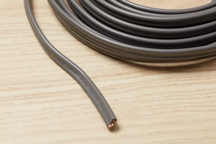
Direct-burial cable is a specialized type of electrical cable designed for outdoor or underground applications. Here are key features and considerations related to direct-burial cable:
- Outdoor and Underground Use: Direct-burial cable is specifically engineered for installations where the cable will be exposed to outdoor conditions, including moisture, sunlight, and temperature variations. It is suitable for underground wiring projects.
- Solid Vinyl Insulation: The individual conducting wires within the cable are coated with solid vinyl insulation. This insulation provides a protective barrier, preventing moisture from penetrating and compromising the integrity of the conductors.
- Moisture Resistance: The primary purpose of using direct-burial cable is to ensure excellent moisture resistance. This makes it suitable for applications where the cable will be in contact with soil, damp environments, or buried underground.
- UV Resistance: Direct-burial cables are often UV-resistant, protecting them from the harmful effects of sunlight over extended periods. This UV resistance helps maintain the cable’s structural integrity and performance.
- Conduit Usage: Depending on local building codes and regulations, direct-burial cable may or may not require conduit when installed underground. Some installations may allow direct burial without conduit, while others may mandate the use of conduit for added protection.
- Multiple Conductors: Direct-burial cables come in configurations with multiple conducting wires, allowing them to carry various electrical circuits for outdoor lighting, landscape features, or other applications.
- Grounding Conductor: Grounding conductors are often included in direct-burial cables to ensure proper grounding of the electrical system and enhance safety.
- Local Code Compliance: It is crucial to adhere to local building codes and regulations when using direct-burial cable. Compliance ensures that the installation meets safety standards and legal requirements.
- Installation Depth: When burying direct-burial cable underground, the installation depth may be specified by local codes. This depth helps protect the cable from accidental damage and ensures a safe and reliable electrical system.
- Applications: Common applications for direct-burial cable include outdoor lighting, landscape lighting, irrigation systems, and other outdoor electrical projects.
Understanding the features and applications of direct-burial cable is essential for planning and executing outdoor or underground electrical installations. Adhering to safety standards and local codes ensures a durable and reliable electrical system in outdoor environments.
Electrical Wire Stripping
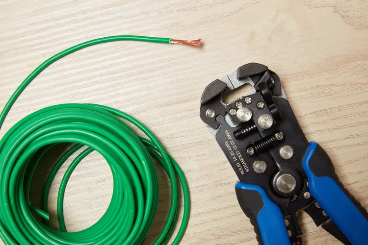
Stripping electrical wire is a fundamental skill for various DIY electrical projects. Here’s a guide on how to strip electrical wire safely and efficiently:
Materials and Tools Needed:
- Wire Stripping Tool: Obtain a quality wire stripping tool designed for the wire gauge you’re working with. Wire stripping tools come in various types, including manual and automatic versions.
- Electrical Wire: Ensure you have the electrical wire you need for your project. The wire’s gauge (AWG) determines the appropriate stripping tool and technique.
Steps to Strip Electrical Wire:
- Choose the Right Tool:
- Select a wire stripping tool that matches the gauge of the electrical wire. The tool should have clearly marked gauge settings.
- Inspect the Wire:
- Check the electrical wire for any visible damage or nicks. If the wire is damaged, it’s crucial to cut it and strip a new section.
- Adjust the Tool:
- Set the wire stripping tool to the correct gauge by adjusting the screw or using the preset markings on the tool.
- Position the Wire:
- Hold the electrical wire securely in one hand, ensuring it’s straight and free from kinks or bends.
- Align the Tool:
- Position the wire stripping tool over the section of wire you want to strip. Align the cutting blades with the insulation.
- Grip and Strip:
- Close the handles of the stripping tool to grip the insulation gently. Apply enough pressure to hold the wire securely without damaging the metal core.
- Rotate and Release:
- Rotate the wire stripping tool around the wire while maintaining a firm grip. This motion helps cut through the insulation without nicking the metal core.
- Release the handles to open the cutting blades.
- Remove Insulation:
- Slide the wire out of the stripping tool, and the cut insulation should stay attached to the tool.
- If the insulation remains attached to the wire, gently twist and pull it off.
- Inspect the Wire:
- Examine the stripped section of wire to ensure there are no nicks or cuts on the metal core. If any damage is detected, trim the wire and strip a new section.
- Repeat as Needed:
- If you have multiple wires to strip, repeat the process for each section.
Number of Wires Allowed in Conduit
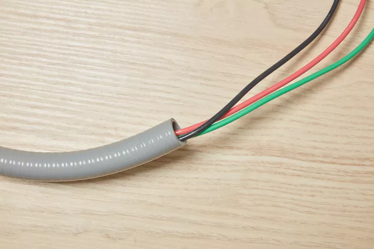
Determining the fill capacity of conduit is crucial for proper and safe electrical installations. Here’s a guide on understanding and calculating conduit fill capacity:
Factors Affecting Conduit Fill Capacity:
- Conduit Size: The internal diameter or size of the conduit is a primary factor. Conduit sizes are typically specified in inches (e.g., 1/2 inch, 3/4 inch).
- Wire Gauge: The size or gauge of the individual wires being pulled through the conduit affects the fill capacity. Larger wire gauges occupy more space.
- Conduit Material: The type of conduit material (metallic or non-metallic) influences the available space. Metal conduits generally have less available space due to thicker walls.
Conduit Fill Capacity Calculation:
- Refer to NEC Tables: The National Electrical Code (NEC) provides tables specifying the maximum number of conductors allowed in various conduit sizes and materials.
- Determine Conductor Size: Identify the gauge of the conductors you plan to install in the conduit.
- Select Conduit Size: Choose the conduit size based on the number and size of conductors. Ensure the chosen conduit size meets or exceeds the calculated fill capacity.
- Check Derating Factors: If the conductors are bundled together or ambient temperatures are higher, derating factors may apply. Refer to NEC guidelines for adjustments.
- Calculate Percentage Fill: Calculate the percentage fill by dividing the cross-sectional area of the conductors by the cross-sectional area of the conduit. Multiply by 100 to get the percentage.
Percentage Fill=(Sum of Conductor AreasConduit Area)×100
- The sum of conductor areas is calculated using the diameters of individual conductors.
- The conduit area is determined from the inside diameter of the conduit.
- Compare with NEC Guidelines: Compare the calculated percentage fill with NEC guidelines. Ensure it does not exceed the allowable limit for the selected conduit size and material.
Wiring an Electrical Circuit Breaker Panel
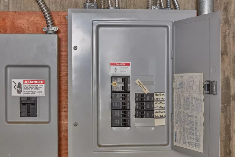
Wiring an electrical panel involves several key steps, and it’s important to approach this task with caution. Here’s a basic guide to wiring an electrical panel:
1. Turn Off Power:
- Before working on the electrical panel, turn off power at the main disconnect or service disconnect switch. This ensures your safety during the wiring process.
2. Choose Appropriate Wire:
- Use wires with the correct gauge for the circuits you’re installing. Different circuits require different wire sizes based on the load they will carry.
3. Install Breakers:
- Breakers protect the circuits from overloads and short circuits. Each circuit in the panel corresponds to a breaker. Here’s how to install a breaker:
- Ensure the breaker is compatible with your panel.
- Switch off the breaker in the “off” position.
- Snap the breaker into an available slot in the panel.
- Connect the circuit wires to the breaker terminals.
4. Connect Neutral and Ground Wires:
- The neutral (white) and ground (bare or green) wires should be connected to their respective bus bars in the panel.
- The neutral wires connect to the neutral bus bar.
- The ground wires connect to the ground bus bar.
5. Label Circuits:
- Properly label each breaker in the panel to indicate which circuit it controls. This makes it easier to identify and troubleshoot circuits in the future.
6. Connect Wires to Main Breaker:
- The main breaker is typically the largest one in the panel and controls all power to the home. Follow these steps:
- Connect the black (hot) wire to the main breaker.
- Connect the white (neutral) wire to the neutral bus bar.
- Connect the bare or green (ground) wire to the ground bus bar.
7. Inspect Wiring:
- Carefully inspect all wiring connections to ensure they are secure and free from damage.
- Check for any loose or exposed wires and correct any issues.
8. Close the Panel Cover:
- Once all wiring is complete and inspected, securely close the panel cover.
9. Restore Power:
- Turn the power back on at the main disconnect or service disconnect switch.
Important Tips:
- If you’re not a licensed electrician, it’s advisable to hire a professional for electrical panel work.
- Adhere to local electrical codes and regulations.
- If you’re unsure about any aspect of electrical panel wiring, consult with a qualified electrician.
Working with an electrical panel requires knowledge and caution. If you’re not experienced with electrical work, it’s crucial to seek professional assistance to ensure the safety and compliance of your electrical system.
Electrical Disconnect Switches
